

Laviduce
-
Posts
264 -
Joined
-
Last visited
-
Days Won
6
Content Type
Profiles
Forums
Blogs
Gallery
Downloads
Events
Posts posted by Laviduce
-
-
------
-
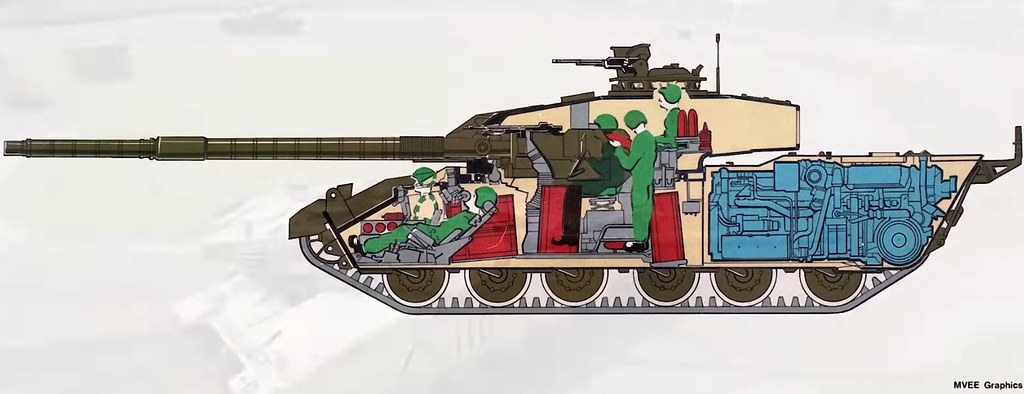
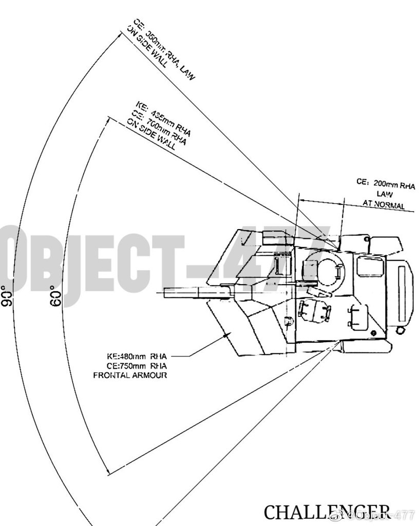
MVEE Cross Section of the Challenger 1 tank:
-
1 hour ago, Ramlaen said:
Your homework is to come up with a reason for Mexico to do joint military exercises.
The joint military excercise would be there to deter US aggression, foster international interoperability and promote peace and regional stability.
-
-
On 7/17/2019 at 9:38 PM, LoooSeR said:
Degenerates !
-
The 19 tons are metric tons. When i present data I always use SI/metric units.
-
9 minutes ago, Militarysta said:
Maybe You have right but the only quite good source is this single CIA raport about erly M1 protection. And FMV raport whit explanation in shape : M1A1HA turret mixed whit M1 hull. Im really far for trusting Zaloga, Osprey publishing etc for obvious resons...
Despit I have my own - Damian - sources about Abrams and despite his personality propably he known the best in CEE about M1 (of cource as civilian can not military).
Of course i know this problem:

But turret in Leopard 2A4 weight 15,500kg and in M1 as I remeber 20 500kg?
Rolf Hilmes gives a turret mass of around 19000 kg for the original M1 tank.
-
6 minutes ago, alanch90 said:
I do not have the full report. I have contacted a person that might have more "direct" information (turret data) on it. If he responds I will post it here. Also, i have no idea what the product improvement program (PIP) is about concerning this document.
- XhaxhiEnver and alanch90
-
 1
1
-
 1
1
-
16 minutes ago, Wiedzmin said:
duh , my mistake , had glanced over it too quickly.
-
Not sure if these has been seen before but can anyone verify this:

-
So the EMES 15 itself weighs 1789 kg, almost 2 metric tons !???
-
1 hour ago, chandieka said:
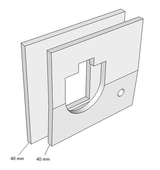
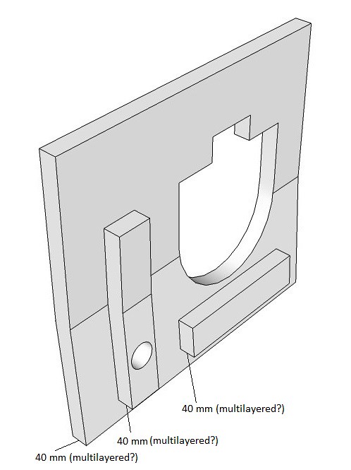
does anyone know why Leclerc gun mantlet don't have any composite armor?
As far as i know the Leclerc mantlet assembly is at least partially "multilayered". According to Froggy the block around the COAX is composite. The mantlet itself might also be composite/multilayered.
-
14 minutes ago, SH_MM said:
The drawings are "fake", but the data is taken from actual declassified documents (~ with a bit of estimated performance regarding the change of armor protection at an angle).
The drawing of the "Challenger 2" is based on the "improved Challenger 1" requirements.
Thank you, that sucks a bit! Also, would you know where the Leclerc protection info (350-430 mm KE for turret) is coming from and if they are legit or not ?
-
42 minutes ago, SH_MM said:
See here:
So the diagrams are fakes ? :c
-
-
-
1 hour ago, LoooSeR said:
Estimates are based on pictures/visual guesses or some sort of hard data that is avaliable for mortals?
The entire project and all these estimates contained within are based on:
- pictures.
- video screen caps.
- scaled blue prints of the exterior of the vehicle that include the dimensions of the vehicle.
- the Tamiya model (which is based on measurements of a Leclerc Serie 2 vehicle).
- visual guesses with plenty of interpolation and referencing.
- basic geometric tricks via CAD using pictures,
- what is known about French and Western MBT design.
- images of the CAD model by DarkLabor (in part).
- documents dealing with ammunition size.
- swedish tank trial presentation.
- the general help and feedback of various other people (i.e.DarkLabor, Froggy, Unwinder66, etc.).
- oh yeah, more interpolation and referencing.
-
Here are my conventional steel plate thickness estimates for the Leclerc S1:
Spoiler Spoiler
 Spoiler
 Spoiler
 Spoiler
 Spoiler
 Spoiler
 Spoiler
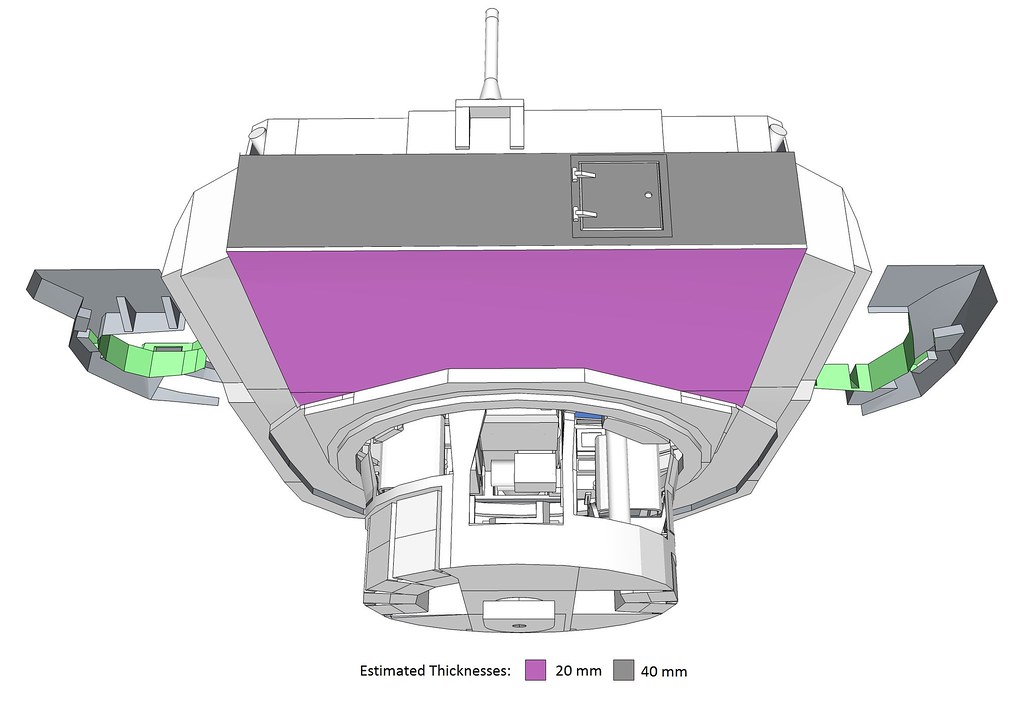
I will discuss the heavy side skirts and the mantlet some more in the next update.
- Lord_James and LoooSeR
-
2
-
8 hours ago, Wiedzmin said:
i'm talking about other images
")
about hull front i think your model is correct(as swedish report showed), but side "flaps" imho looks very strange
You mean the other images on the page ?
I am not totally sure how to resolve these "flaps" any other way without making it worse.
Spoiler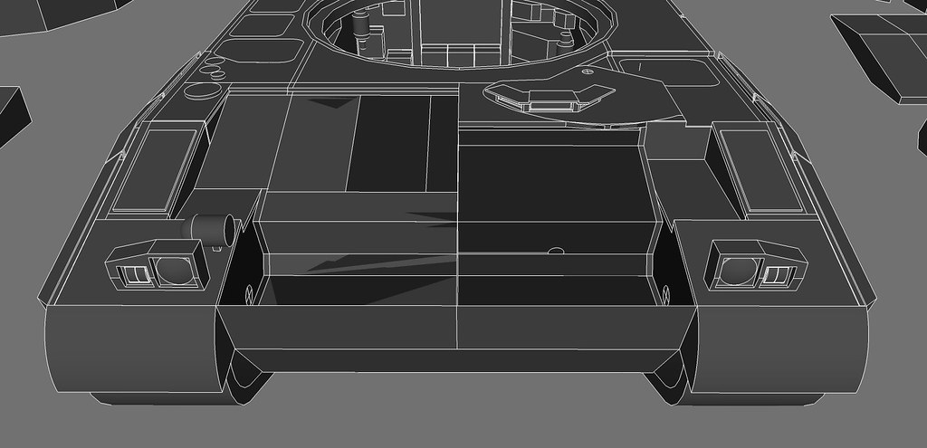
-
1 hour ago, Sovngard said:
- There should be two pipes connected to the turret roof : one for the air inlet and one for the exhaust outlet (your S1 model features the S2 hot air exhaust pipe).
- The attachment point at the level of the gun elevation gear should be drastically improved.
- The hull special armor cavity extends downward from the hull front welding line (which doesn't delimit the bottom of the special armor cavity, the suspension recesses are a small clue).
- Regarding protection of the gun shield/mantlet/mount/square frame, there is not enough information available in the public domain to make any conclusion/accurate modelling.
1) I did not bother to go into details with the air handling/conditioning unit because it was not part of objective and I did not have enough information to go by. If you have more detailed information so i can complete /correct the AHU I would be grateful if you could provide it to me.
2) I was not trying to go into details here given the lack of information. I wanted to give the approximate size and location of the mechanism. Could you please elaborate on what part seems to be off?
3) I still do not understand this part.
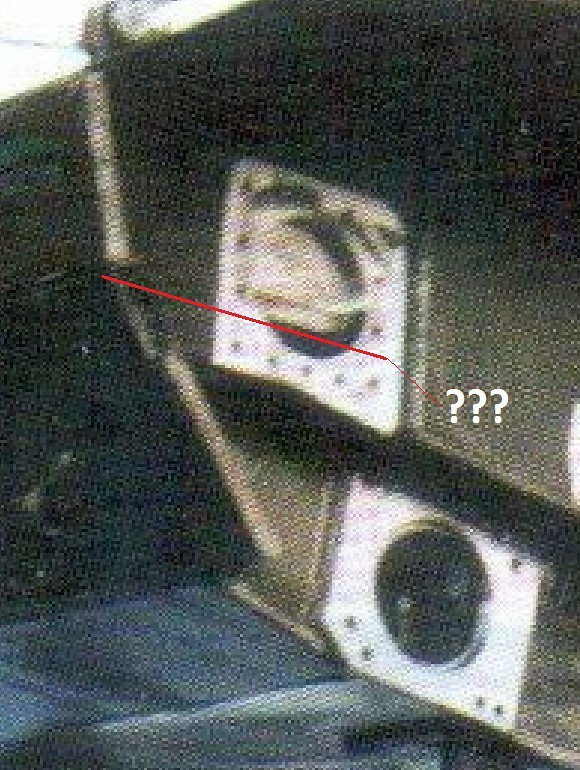
4) The mantlet setup was derived using the following images:
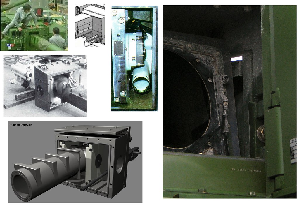
-
After feedback, it might be best to differentiate between different types of "special armor" regions. I am very certain the turret bustle special armor (orange) is not the same as the primary special armor (red) or the side front hull special/spaced (?) armor (green):
Spoiler Spoiler
 Spoiler
 Spoiler
-
2 hours ago, Sovngard said:
So, you have to correct your 3D model.
I do not understand what i should correct. Could you please explain ? From what i gathered from the picture, among other things, was that the lower boundary of the special armor bays 1) seems to be level with the hull floor and 2) the lower edge of the front hull is more or less the lower boundary of the special armor bays.
-
3 hours ago, Wiedzmin said:
thank you

about you schemes with special armour, turret right "cheek" seems to have some sort of weakspot in bottom part(protection of left and right asymmetrical by height? or maybe it's not that obvious on early turrets)
can you share this/those scan/scans ?

such an arrangement of special armour is very doubtful due to uneven LOS imho, it can be spaced armor, but not special
Here is the turret of the model from another angle:
Spoiler Spoiler
 Spoiler
 Spoiler
 Spoiler
 Spoiler
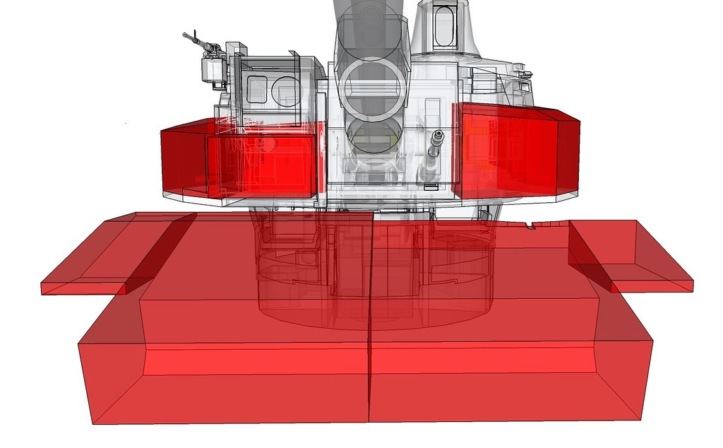 Spoiler
The front turret is of the series 1 tanks. This changed in series 2 and again with series XXI. Darklabor made these a while ago to illustrate the changes:
Spoiler Spoiler
The uneven line of sight thickness of the left front hull side flap have also concerned me. As you can see the right side flap has a more even distribution (mainly because of the fuel tanks). As you said these side "flaps" might just be spaced armor.
The swedish tank trials mockup did not include them, which could mean that they are not special armor.
Spoiler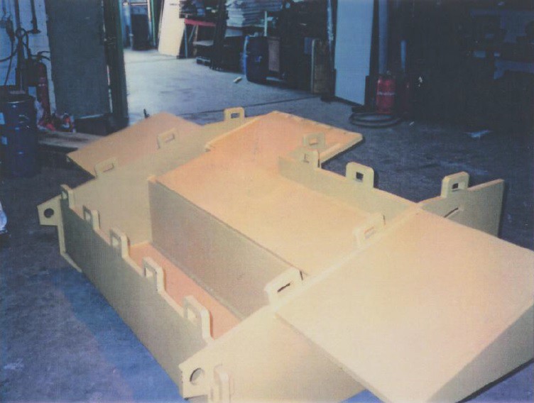
As you have seen in a previous post my earlier rendition of this modules had a more regular LOS thickness because of me placing a tiny fuel tank in that location as well. But looking at the insert bays and what was pointed out in an earlier post i removed the (mini) fuel tank. It made little sense to have a 4L fuel tank in that location.' In the image below, the upper right center shows the straight line shadow of the side wall of the insert bay:

Here is the "high res" image of the hull:

-
13 minutes ago, Sovngard said:
The bottom right picture reveals some interesting details.
Oh, yes ! I used a high res scan of that image to get my lower boundaries for the front hull inserts among other things.


French flair
in Mechanized Warfare
Posted
Test Line-Of-Sight Thickness Diagram overlay at +10 degrees of the Leclerc S1 model:
The overlay diagram is just a test. Considerable more fine tweaking has to go into it before i can release the rest. The MATLAB program measures the LOS thickness in 10 mm intervals over any part of the crew compartment using pixelated slices of the vehicles in a .png picture format. I have tested it several times with smaller inputs and it seems to work, although it has to process for 30+ minutes for each aspect. Note that this is not the vulnerability diagram. As one can see the left front hull LOS is not visible because it went below the value color threshold. Other color coding schemes are available, which i might use instead of this "hot" color scheme. The values vary from a couple of centimeters to a couple of meters. The tracks and the main gun are the primary contributor for these large differences. The program and/or the slice diagram could be adjusted to get rid of the main gun and track assembly so the program generates a more reasonable output. Either way, more fine tuning and work is required to get the diagrams to a presentable level.